by  Chupo_Cro
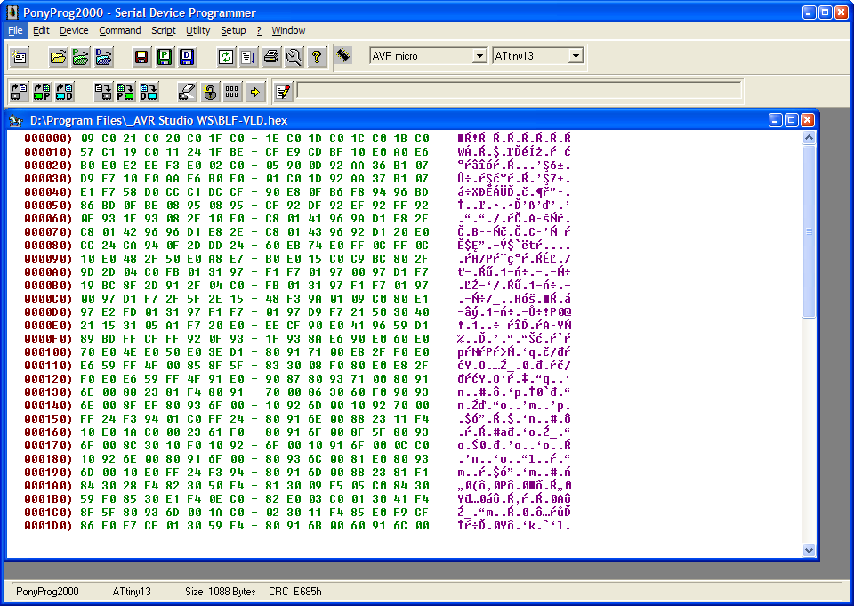
This is what you get after obtaining the hex dump of some unknown firmware. Although it could be partially readable (by very experienced people) the data has to be disassembled. This is BTW hex dump of the Tido's BLF-VLD and reconstructing the original Tido's source code written in C from such hex dump would be a *very* complicated and tedious task. There's only the beginning of the hex dump in the picture.
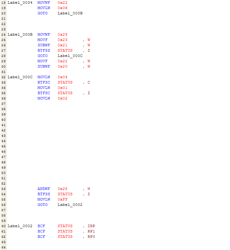
The next step would be to disassemble the firmware with disassembler strictly targeting the µC in question. This particular disassembly is not from ATtiny and not even from some of Atmel's µCs but rather from one of the Microchip's PICs - 12F629. The instruction set and the whole architecture is very different between those two microcontrollers, however the example will be sufficient to get the picture. I've left some space in disassembly to later insert the comments. As you can see, the disassembler made some labels identifying the addresses used in jumps and it used the names of some known internal addresses. Unfortunately the label names are just generic (read: meaningless), that is because the disassembler doesn't know what was the purpose of those instructions - it can only decode one instruction at a time and only human can decipher the program in its entirety.
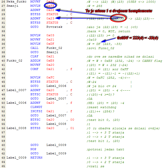
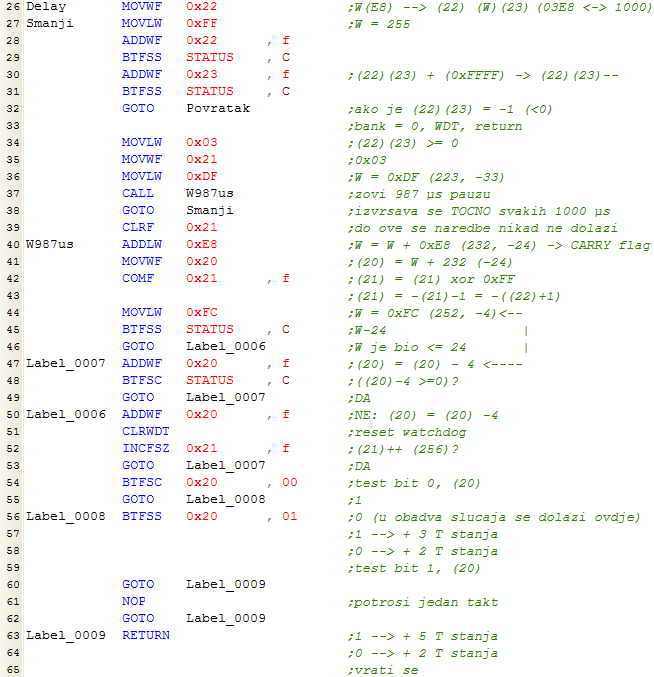
Here you can see the labels after i replaced them by something meaningful and the comments I made so the code could be human readable (the comments are in Croatian but that isn't important - it's just an example). I could, of course, write the comments and the labels only after spending significant time analyzing the code you see. I don't remember how much time I spent disassembling this very routine but it took quite more time than for example writing something as 'if (a>b)'. And that's exactly what this routine is!! :-) Someone who wrote the firmware probably typed something as 'if (a>b)...' and the compiler included this part of the code. After examination it can be seen that the routine compares two numbers stored in the locations (20)(21) and (22)(23) according to the 'mask' stored in W register. The comments in the lines 47-50 are explaining the input mask. Comparing can be performed by storing two numbers at the before mentioned locations, loading W with the desired mask and calling the routine. That way we can test if the 1st number is greater than, less than or equal to the 2nd number (in fact the routine can test even >= or <= because we can set more than one bit in the mask). So what the original source code looked like? The answer is: We don't know! We even don't know if the original source code was written in C, BASIC, some other language - or even directly in the assembly language!! We can however - by looking at the instruction in the line 20 - guess this was the program written in some higher language. Because human programmer in this case wouldn't jump right onto the very next address in memory - he maybe would in some time critical routines - to deliberately spend a few processor T-states but that is another story... Now, try to imagine how much time would someone have to spend to disassemble the firmware consisting of 800, 900 or 1000 instructions where there are dozens of routines that has to be first deciphered to be able to only follow the code. I'll give another example to emphasize the complexity of the task. BTW, at the end of the code we can see the compiler (I later discovered it was MBASIC or mikroBasic - I don't remember) cleared IRP, RP1 and RP0 and 16F629 has only RP0 - that could mean someone targeted the wrong µC or the compiler was 'badly written compiler'.
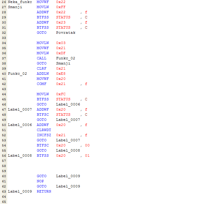
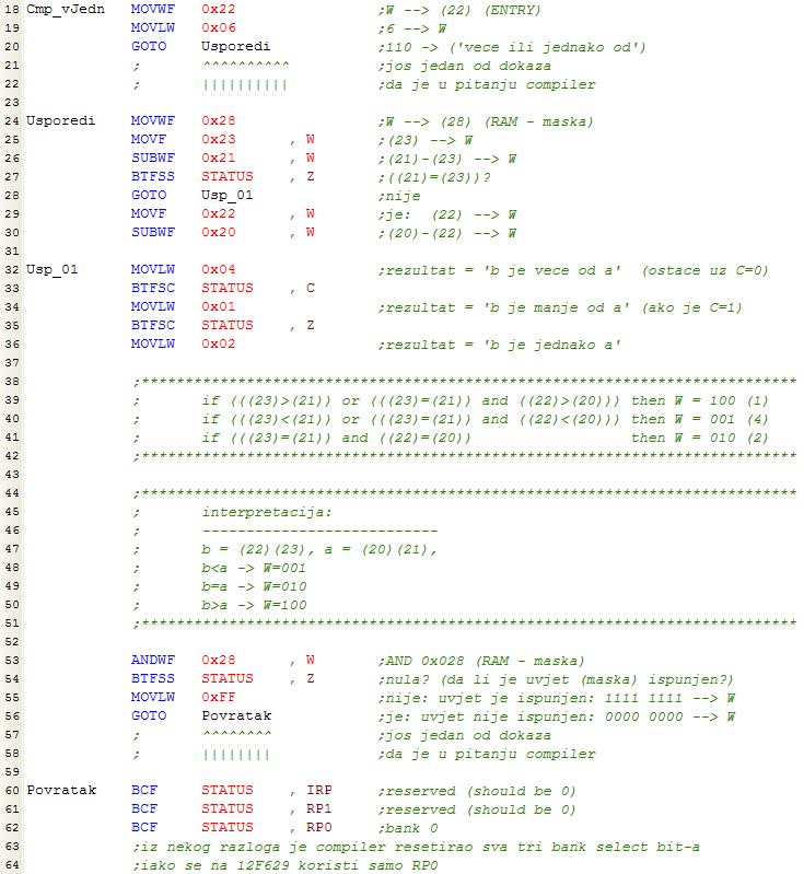
Here is another example. Some unknown routine from the same firmware (it was BTW from device to record the IR code sent by TV remote).
After some deciphering...
It was Delay command. You can see the label W987µs that I made - that is 'wait 987 µs'. I spent quite a time disassembling these not so many instructions as deciphering this routine involved precise counting T-states spent in the loops.
I hope these two examples made clearer how complicated would be to disassemble a firmware containing maybe 1000 instructions - only to make some small changes in the original code. In case of most flashlight drivers it is much simpler to write the new firmware from scratch.